 |
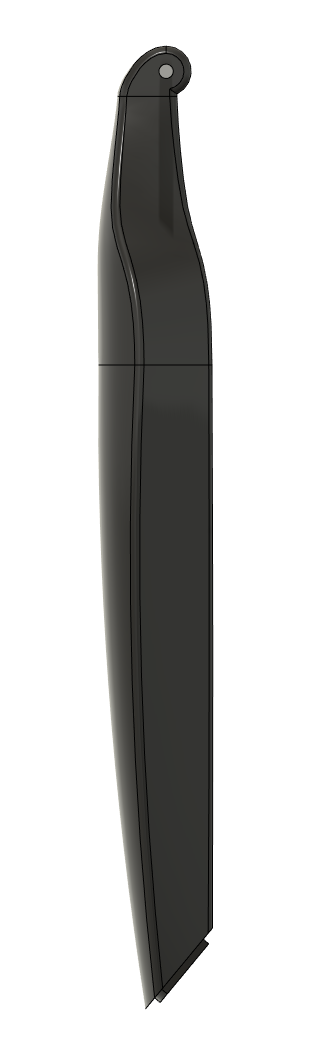
| Orthographic side view. |
I still am not sure what is the best way to model these smooth contours; I initially started off by drawing a top-down view of the leg, thinking I would then extrude this profile and then cut it from the side with another profile like I did for the glasses I previously modeled. I quickly realized this would not work that well since the legs don't have parallel sides.
I backtracked and then decided this would have to be done with lofts. Using the top-down sketch as a guide, I created several cross-section profiles along the leg for the loft to follow and then created the leg out of two lofts. The modeled leg is definitely not perfectly accurate to the real leg as the real one has a smoother curve along the entire outer face and pinches in faster on the inner face. If I were to do this again I would use 3D curves and guide each edge with a rail. Also, at the hinge the curve should be more gradual and not bend in as quickly.

A video of the modelling process:
And a render:
 |
| Nice render with the tripod open. |


