Showing posts with label Electronics. Show all posts

Tuesday, July 26, 2022

Microphone Amplifier: Shielding

My friend owns a ribbon microphone, which have notoriously low output levels even after their internal transformers steps up the output, and always need to crank the gain up to the max and use noise reduction to get anything usable. A common solution is to use an in-line preamp such as the Cloudlifter and the FetHead. I wanted to see if I could make my own amplifier after seeing a small snippet on ribbon microphone amplifiers in the Art of Electronics

After a little bit of Googling, I came across reverse-engineered schematics for aforementioned amplifiers. They both use JFETs in a differential pair, which allow for the gates to be biased at 0V straight from the microphone, and are powered directly off of phantom power with the phantom power resistors as the load. The Cloudlifter has a cascode configuration of JFETs, while the FetHead is just a single device. Someone already made a FetHead clone, and to keep my project simple I essentially cloned this. I added a few changes to my PCB:

  • Added a footprint for a two channel ESD diode device
  • Added places for emitter degeneration resistor if one wants to add them
  • Used the connector that has the shield separated from ground both the input and the output XLRs
    • Added jumpers that allow for configuration on how the shields are connected to each other/to ground
I was really interested in seeing how to properly shield the amplifier and the effects of grounding the shielding at the amplifier versus not. From several videos I watched on connecting up the shield in general for cables (not just audio and XLR), the idea is to form a continuous Faraday cage to keep out noise. You want all the shields joined through the cable to the chassis of all the devices in line. Whether you ground this shield at all points vs just at one point or only to earth or not at all (no DC connection but AC coupled) I'm still not clear on. With all the jumpers I wanted to test what happens under different conditions.

KiCAD Schematic.

I sent the boards out to made and ordered the parts from Mouser. A week later, everything showed up at my door and I filmed a making-of video just for fun:

I still got the footprint wrong for the ESD diode; I originally chose a SOT-23 part but changed to a lower voltage part just before sending out the design and forgot to change the footprint for SOT-523. Thankfully the part still soldered into place without much issue.

PCBs.

Parts.

Assembled.

The metal box I originally thought of putting the amplifier into ended up being just a little smaller than I thought, causing some interference with the connector screw holes. For now there is no enclosure, making proper shielding tests impossible. However, I can still generally test the amplifier. I handed off the amplifier to my friend and we saw significant gain (I don't really have any equipment setup to do a proper measurement of the absolute gain at home anymore and definitely don't have any to do a portable measurement.). There was very audible noise when there was supposed to be no sound but we'll need to figure that out another time. Some initial experiments with joining the shields on the board and to the ground gave inconclusive results along with a jank foil shield. The cable being used is also of questionable quality.

Tuesday, May 3, 2022

iCE40 FPGA Tinkering

After my very short experience with getting the Vivado toolchain setup to use the the Pynq FPGA board a few years ago, I've decided to get back into doing some projects with a FPGA again. I only ever got around to blinking an LED before putting the board aside; I had no solid projects in mind to make. The only reason I tried using it was that I was able to get one for free and it is the board used in the digital design class at Berkeley. I know it is a very powerful device and has lots of nice peripherals directly on the board so I may come back to it in the future. (Most digital design time is really spent in simulation anyways so the exact hardware doesn't matter that much.)

But man, the complete Vivado toolchain is nearly 80GB installed, and the bloat of everything with respect to it did not sit nicely with me. So recently I set out to find a different FPGA with a nicer ecosystem. From other projects I've seen online the first one I looked into and eventually settled on was the Lattice series of iCE40 FPGAs. The configuration bitstream has been reverse-engineered and a series of open-source tools have been developed for using these iCE parts. Synthesis, place-and-route, and bitstream generation all can be done through some simple steps. (Most other FPGAs still have locked down bitstreams and is why you need to use vendor-specific tools to do the synthesis and place-and-route. Being tools that are developed by large corporations with lots of money, they may/probably have better outputs from these steps (e.g. more optimized synthesis, better place-and-route of logic cells for better timing, etc.).)

I picked up a UPduino board with its iCE40-UP5K FPGA and installed the APIO ecosystem for the development and build toolchain. APIO makes it super convenient to develop for these FPGAs as it bundles together all of the open source tools.

General setup process (so I don't forget it; recently I had to re-lookup how I setup my STM32 toolchain back in 2018 so if I wanted to use them for a real project I would be able to):

  1. Install APIO
  2. Generally followed this guide.
  3. Initialize project with apio init --board iCE40-UP5K -s
    1. -s allows us to customize the SConstruct file so that we can the build process look into subdirectories for the source files.
  4. For simulation use apio sim
    1. Simulates from *_tb.v files
  5. apio build to build the verilog
  6. For some reason apio upload would not work for me; I suspect there is a PATH problem with my python setup (error: 'WindowsPath' object is not iterable)
    1. I just manually uploaded with iceprog -I A [path to bitstream]
Within minutes I had some blinky LEDs going current controlled by the internal LED peripheral, and running a simulation was relatively straightforward. Next steps are generating PWM and then maybe generating some VGA signals. Still not sure if this the best platform to be using but for small projects the simplicity is nice.

Aside: Some time ago I had did about a day's worth of tinkering with Verilog and getting simulation setup with iverilog and gtkwave after reading blog posts on zipcpu and gaining some interest in HDL again. Getting everything setup on Windows is slightly annoying with all the random things on my path and multiple terminal and shells installed over the years (got the windows CMD, git bash with mingw, msys2, and cygwin).

Tuesday, January 4, 2022

Switching Buck Regulator: from theory, through simulation, to implementation

I had a much longer introduction written up in my draft document of this but now looking back at it, it's a little unnecessary. To summarize my thoughts; in an attempt to provide some motivating direct applications of what I have learned in classes, I want to begin writing about some projects that directly apply the theory from class to something more tangible. Hopefully they can demonstrate real-world issues that one can run into when implementing these concepts for real. This is also a good excuse for me to refresh my memory on many of these topics and provide a good written reference to hold on to.

Any errors/things that are unclear are on me. Hopefully there aren't too many and I'm not saying anything too wrong. 🤷‍♂️

Part 1: Basic Buck Converter Theory 

This is a quick crash course of DC-DC switching buck converters using my knowledge from EE113, Power Electronics, and EE128C, Feedback Control Systems. In my power electronics class, we went over the basics of the most common types of power converters. Hopefully this is a good refresher for me and lets me put theory into practice. [This write up is really mainly for me and kinda but doesn't really begin from the very basics; it also tries to follow a linear progression to the best of my abilities but there many subtopics that loop back on themselves.]

In this design example I want to go through the basics of a buck converter again and then apply some feedback/controls knowledge to making a converter that can deliver a set output for a varying range of inputs. This will also allow us to look at the transient response of the output of the regulator, from startup and changes on the input, to sudden changes to the output load. Everything I write will be from what I remember from EE113/my notes/the textbook Fundamentals of Power Electronics by Robert Erickson. I didn’t look at the textbook that much during class, but as I now reference it for this project it reads very clearly and is an excellent reference.  If anything is unclear here, definitely take a look at that book.

Sunday, May 17, 2020

Bench Power Supply

Yesterday I put together a simple wood box for a DIY bench-top power supply. I had the electronics for awhile now (I forgot when I bought them, but it was probably around a year ago) but just never put them all together. I bought a used 24V, 13A power supply and a DPS5005 front panel/regulator.

I put together a quick CAD model of the box using slot construction and 1/8" wood:

The back part would be on the ground so the front is tilted up.

However, I realized after making this model I probably didn't have enough 1/8" plywood to make all the faces. I redid the design to have panels slot into thicker material and came up with this:
3/4" wood for everything but the front and back panels.
I flattened everything out and just ran contour toolpaths on everything. I had to break up the parts into separate programs because I wanted to use the edges of wood scraps where there was only enough room for some of the parts.


It took awhile to cut everything because I had to change stock between nearly every part. After cutting it all out I screwed the box together:

Front panel cut out.
Bottom plywood is a little scuffed.
Back panel.

I didn't realize how thick the banana plugs I ordered were (I was always imagining the ones on  commercial power supplies like Keysight bench PSUs), and the little cutouts around each pair of plugs are a little small.

I have small DC-DC boost converter on the way to boost the 24V to 48V since the DPS5005 can take in up to 50V. The left most output is the output from the DPS, and middle is 24V out, and the right will be 48V out (it might actually never be useful and it could just be another 24V out).

Also: a fun picture of some more endmills I bought a few weeks ago (I just had to buy some more real brand name 1/8" endmills after seeing how good actually sharp cutters are). I have yet to try the single flute cutters on acrylic but the two flutes ones cut the wood in this project perfectly.

Sharp.

Thursday, November 28, 2019

DIY Numpad: Enclosure

The numpad plate and PCB didn't fit into the test case I had cut out mainly because the encoder (which sticks off of the PCB a little bit) didn't fit into the slot I originally designed into the case.

To fix this, I made the slot larger and added a little more margin for the plate and PCB (added 0.5mm to all sides of the cutout). I also made the case deeper and added a cutout for the underglow LEDs at the bottom of the PCB. I'm not sure how I want to do the hole in the bottom for the LEDs to shine out of, but a simple hole will do for now. I considered a grid of circles or a grid of hexagons but will have to try that out at a later time. The bottom may also become some frosted acrylic or something like that.

New case design.
After cutting it out of 1/2" MDF (I need to find some nice wood to make later cases out of), I got this:

Case!
My stock was most likely not level so one side was slightly deeper than the other, but the plate and PCB fit. You can see that on one side the lip for the plate is slightly higher than the other side:


I had to manually cutout a slot for the USB-C connection:
Finding where the hole should go.
Not the prettiest but good enough.
I didn't cut out the top plate wood yet (the piece that covers the plate and adds a lip around the keys), but I wanted to test screwing everything together:

Pretty good!
Temporarily using some keycaps from my Quickfire Rapid.
Bottom side. The LED under the encoder is not exposed.
And after adding in an encoder knob I had lying around the numpad looks pretty good:

Clean.

Next steps are to get a prototype of the top piece of the case made and get the RGB LEDs working. On the side I need to find and try out some different pieces of wood for making the final cases.

Thursday, November 14, 2019

DIY Numpad

In the summer I replaced all the switches on my keyboard from Cherry Blues to Hako Royal Clears and wasn't sure what to do with the rest of the switches. Why not build a numpad!

I first began making a few drawings of what the numpad should look like. I wanted to have an encoder and the layout would be 4x5. The size would be dictated by the size of the largest PCB I could get manufactured for cheap (100mm x 100mm). This is perfect for a fully filled out 5x5 layout, but I wanted that encoder and an angle in the design.
Layout.
Render of the PCB from KiCAD.

With a general concept in mind, I went over to Fusion 360 to generate a CAD model. A few iterations later and relearning how to CAD in a not entirely garbage manner, I had a workable design. I still don't know what is the best way to create the sketches and dimensions in a way that is easy to adjust later, but I tried my best.
CAD Model of the case.
At the same time I began putting together a schematic and layout for the circuitry. The microcontroller of choice was the ATMega32u4, since it is the most popular microcontroller for the QMK firmware I plan to use. A few switches, diodes, and LEDs later, I had something ready for shipout:

With parts and boards on the way, I tested out making the case for the numpad (Oct 12). The cutting operation began with an adaptive clearing for the pocket in the middle:
Adaptive Clearing with 1/8" endmill.
Afterwards, the program cut out the inner lip for the plate, then the drills for the corner screws, and finally the contour operation for the outside:
Inner lip, drills, and outer contour operations all done with 1/8" endmill.
The finished cutout (the part was not removable since I tested it out in 3/4" MDF while the model is 1/2"): 
Test cutting of the case in MDF.


I laser cut out some stencils for solder paste and reflowing the parts (Oct 29):
Stencil laser cut in 0.003" Duralar.

Spreading the paste.
After reflow:
Didn't have the USB C connector at the time and had to hand solder that later.

For the plate, I wanted to use aluminum. I never cut aluminum before on my CNC but now was a great time to try (Nov 11).  The stock was 1.5mm thick 5052 aluminum, and I used a 1/8, 2 flute end mill and some Tap Magic. The feedrate was 20 IPM with 0.012" depth of cut per pass:
Test cutting out the holes of the switches.
Got a little too ambitious trying to see if it would fit in the bottom hole with 1/16" radius corners (datasheet max is 0.3mm).
Switch fits in the dogbone'd hole.
After that successful run, I went on to the whole plate. I slightly modified the dogbone geometry for the corners so they would be smaller. My first dogbones in the cutting test I manually put in, but there was a nice add-in for Fusion 360 that I used to add dogbones for the whole plate that can be found here.
1/8" 2 flute endmill for all operations.


After exporting the G-code and continuous application of Tap Magic for cooling, I got this:
Messy.
With some clean up:
Removed most of the burrs.
Switches all fit!
The plate dimensions in CAD were 108.00 mm by 104.43 mm. The actual cut out plate came out to 107.9 mm by 104.7 mm. Not bad.

Before soldering all the switches to the PCB I realized there was going to be a clearance issue with the USB C connector with some types of USB C cables that have a thicker housing:
Uh-oh. USB C connection collides with the plate.
Soldering the PCB to the bottom of the legs for the switches (instead of the PCB sitting flush with the the bottom of the switches) gives just enough room for most cables to fit. It also turns out the cables I bought were very low quality and in some ports the USB-A side is loose, which led to my numpad being intermittently connected. When I used a snug cable or a C to C cable the numpad works fine every time.
Plate and PCB all together.
Backside.
The basic QMK firmware was easy to get working, and I was able to get keypresses on the switches and volume control on the encoder with minutes. However, the RGB LED control turned out to be a large pain in the neck. The APA102 driver in the QMK firmware has never been used before by anyone else's design and it clearly shows. Right off the bat, the base file does not compile since there was an unmatched parenthesis. I'm going to need to put some time into fixing the code and hopefully can get some nice colors running.

Saturday, July 13, 2019

High Power LED Driver

I've been wanting to create a some drivers for high power, high CRI LEDs to use as lamps, and last month I designed and made a few that work fairly well. Made a few blunders and the original design had to undergo a few bodges but the base idea works.

I originally wanted to create a boost converter from scratch to drive the LEDs, as the LEDs require about 34V to run a full brightness. It would have been a good learning experience to setup basic control for the switching and the circuit topology isn't that complex. However, since I really wanted to use these day to day and the power being delivered was around 50W, I decided to just go ahead with a boost converter chip.

I considered a few: the AL3353 looked nearly perfect for the job, as it offered current sensing and was designed specifically for LED boost applications. However, the switching frequency was rather low and a large inductor would have been needed. I looked a few others, and eventually settled on the LM3478. This chip was designed to be a general purpose constant voltage boost converter. I wanted to modify the feedback path to be constant current: a small current sense resistor with a current sense amplifier to reach the high feedback reference voltage of 1.26V:

Seems like a good idea at the time. Schematic could also be better formatted.
The microcontroller would create an offset voltage that was added to the amplified current sense voltage so that the current could be regulated. I would quickly realize my implementation was flawed.

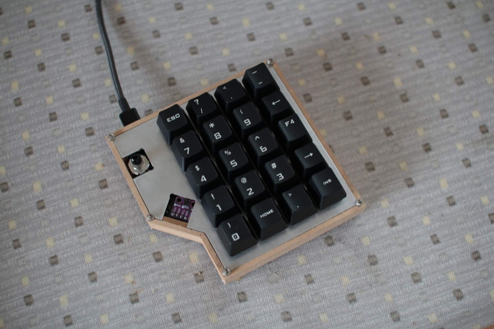
For the microcontroller (to control the brightness levels and regulate temperatures) I used the ATtiny1616. This was really nice to use as it was relatively cheap compared to older ATtinys, had a DAC (which I needed for the offset voltage), and had a one-wire programming/debug interface (woo!).
Programming with
ATtiny dev board
The LEDs I used were high CRI Cree LEDs: the CMA1825 series in 2700K and 5700K. I also ordered a few cheap 50W and 100W LEDs for testing.

Cheap LEDs
Cree LEDs
I did the board layout following the TI WebBench design, soldered up the boards, wrote a little code and voila:
Light!
I was a little surprised this worked this well. Almost immediately after sending out the board I was a little concerned the boost converter driver would not like the new feedback setup, especially at the high frequencies it was running at. I looked at the datasheet for the INA199 current sense amplifier I was using and uh-oh:
Not high enough.
Should have looked a little more closely before I chose this part. The LED did light up and I could control the brightness. But, there was some coil whine at low brightness, and at high brightness the switching MOSFET and inductor quickly became very hot. Over 80C hot. 

I had some time today to take out my feedback path and just setup a voltage divider from the output to the feedback pin as intended, and the whine disappeared and the temperatures didn't rise much over room temperature.
Potentiometer from output to feedback pin.
Light! Again!
Guess I'll have to setup a couple of potentiometers for dimming (the functionality of the board doesn't change, just the brightness can no longer be programmatically controlled) to prevent over and undervoltage for the LED.

I bought a new heatsink and lens combo and tested it with the cheaper LEDs:

The yellow edge on the beam is a little gross and may just not use the lens reflector combo and use a larger diffuser.

7.21.2019 Update:

I bought a bowl from IKEA to act as a reflector and got rid of the lens to get a wider beam that was more even:

For some reason the board I was using developed a short across the input power terminals but I can't find where it is for now. I tested the input capacitor and that was okay. Will have to investigate more later. For now I just swapped over to one of the spare boards I had put together and flashed over the firmware:

Works very well!
Let there be light!
Since I don't want to get a new board made, I'll probably find some sort of digital potentiometer to use for brightness control and hack it in for the feedback.