Wednesday, April 1, 2020

DIY Numpad: First Completed Prototype!

I machined a top part of the case out of some oak wood; the plank had some internal cracks and as a result after being cut out it broke into a few pieces (I'll need to find some better and denser woods later):
Oof.
 I glued the pieces together the best I could and applied some polyurethane finish:
Uncoated.
I put in the 4-40 threaded inserts into the holes (they fit snugly with a little of pressure) and secured them with a little bit of superglue:
Perfect fit.
Screwing the top on:
Not too bad.
I now need to make the body out of the nicer wood too, but for now seeing everything together was big moment in the project.

The glued edge doesn't line up. You can also see the chipped clear plate with the poor surface finish.
I'm also a ran a few tests in acrylic to see try to find the right feeds and speeds to prevent melting. I simply can't run my machine fast enough with my current lead screws (10 TPI) even at the router's lowest speed setting. I broke two endmills, both due to lost steps from resonance. I need go faster than 70 inches per minute but am unable to consistently. I need to install some bearing blocks to support the axial load (so it's not on the motor directly) and pretension the lead screws.

Okay finish on the floor but not on the walls.
Chipped the end mill on the screw.
I could get good floor finish with lower optimal loads and smaller stepovers even at low feedrates, as expected. I tried a finishing pass but the feedrate wasn't high enough and I just got a fuzzy edge.

I also tested out engraving with a V bit (for when I want to engrave a section of the aluminum plate):
Wingman.
Will need to see what to do about the acrylic; I want to find what the true upper limit of my feed rate is after fixing the current lead screws before looking at getting new lead screws.

Thursday, March 26, 2020

DIY Numpad: More Case Prototyping (and Nixie Clock Case)

I did some more prototyping of the case several weeks ago using a 3D printer (first time I actually used a 3D printer) to test out an opening for the USB port:
Freshly printed.
This was the second time I printed it; the first time I didn't have a brim and one of the edges peeled up. The screw holes are undersized as expected since the plastic will have some squishing outwards and after cooling there will be some internal stresses, but I don't plan on using this right now so it is fine. The plate fit on it just fine.

Since this week is spring break, I was able to go home and use my CNC. I made a few changes: I got a new spindle after the previous one died (and it wasn't worth replacing brushes and bearings), bought a new spindle mount, and finally mounted my e-stop button.
New router (variable speed!) and mount.

E-stop.
Yesterday, I finally got around to making the case for my nixie tube clock. I did a quick test pocket before making the case:
Test pocket. 3/8" straight cutter.
I used a facing operation for the top with and an adaptive clear for the pocket. I made a few changes for the final case: changing the chaining for the facing operation from smooth to linear (so the tool wouldn't suddenly engage more material in the smooth curve outward), leaving a finishing pass for the adaptive, and adding a 2D contour to cut out the box from the stock.

Not bad.
This looked really nice but there were a few problems. The x-axis lost steps in the middle on the operation twice and I had to re-touch off to re-zero my x axis. This was due to some resonance in the x-axis leadscrew, and I had to add some damping to the screw with my hand. I need to make a bearing support from the other side of the screw, or use faster leadscrews (for a future upgrade). Secondly, my finishing pass was too aggressive (0.02" axial and radial stock to leave) and I think the thick double-sided tape had more deflection than that. I tried to pocket the entire depth of the pocket for the finishing in one pass and the final pocket was exactly 0.04" too thin. As a result I had to manually route the pocket a little bigger for the PCB to fit.

Pocket too small. Looks nice though.
I had to sand the top to remove some gouges in the stock.
Gained a case but lost a tube.
In my carelessness of handling my clock a tube dropped onto the ground and broke. A replacement is on the way.

Cracked tube.
 (update: new tube installed!)


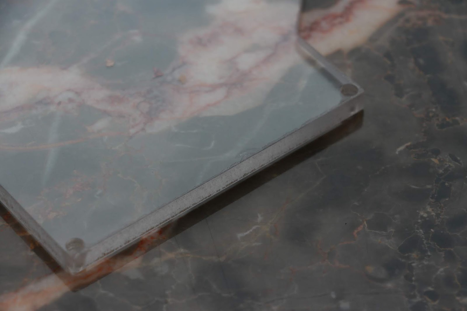
Today I just wanted to run a quick job to test out a clear plate on the bottom of my numpad case (last week I got the APA102 RGB LEDs to work with SPI so now there are nice colors to see). I had some 1/4" acrylic to test this out in.

My first attempt led to some chip melting and the edges have poor finish (was at ~10k RPM and 45 IPM). I thought I was going fast enough but I guess now. Also the bore for the screw heads to sit in is undersized likely due to some melting.
Plate.
Sad edge.
I tried to go faster for a second time (60 IPM in program, with 120% feed rate in LinuxCNC, which comes out to 72 IPM) but still got melting. I held a brush up to the bit the whole time and this helped prevent chips from accumulating on the bit. I think the melting is because the acrylic was probably extruded and not cast (I don't know exactly what type it was, but it had clear plastic covers).

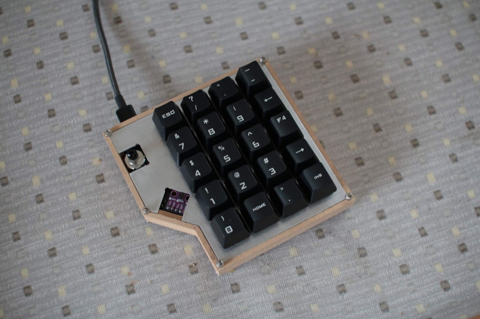
I had to use a drill to clear out the holes for the screws, but after that I could test fit it:
Not bad.
The edge finish definitely needs work, but it should be easy to fix by changing acrylic type and putting in a dedicated finishing pass. I still need to make the top part of the enclosure and put in threaded inserts for the screws to grab. After that, if everything looks good, I will make more cases out of nice wood and not MDF.


I don't know how long I plan to stay at home due to the coronavirus outbreak shelter in place policy and school all being moved online now. If I stay I should be able to make more progress on this case and finish it up.

Tuesday, December 24, 2019

Step Stool

Yesterday I put together a quick project: a step stool.

Finished product. Step stool!


My mom needed a small stool to go in the kitchen so she could reach some of the plates stored on higher shelves, but it had to be short enough to pass under the lower cabinets.

Finished CAD model.
Legs, also with dogbone for the inner corners.
CAM.
Time to cut it out on the CNC. I used some crappy plywood I had laying around; I wish I had better quality wood so it would look nicer but this wasn't too bad. During the cutting operation, the router's rotation started becoming intermittent and stopped working altogether. I thought the router finally failed but opening it up revealed a disconnected wire. After reattaching it and cleaning out some of the accumulated dust, the cutting went smoothly.

Cutting complete.
Free parts.
The tabs were a little large in one dimension and I just used the router to hand remove a bit of the wood for everything to fit together. Once I fixed that, I friction fit everything together with a hammer. Some sanding and a coating of wood poly later I had the final product:

Step stool in the corner.
I got really lucky that the plywood was only around 0.7 inches thick while in CAD everything assumed 0.75" thick wood. This effectively added just the right amount of margin to the tabs and tab holes to account for CNC's lack of rigidity. In the end, it all turned out nicely.

Thursday, November 28, 2019

DIY Numpad: Enclosure

The numpad plate and PCB didn't fit into the test case I had cut out mainly because the encoder (which sticks off of the PCB a little bit) didn't fit into the slot I originally designed into the case.

To fix this, I made the slot larger and added a little more margin for the plate and PCB (added 0.5mm to all sides of the cutout). I also made the case deeper and added a cutout for the underglow LEDs at the bottom of the PCB. I'm not sure how I want to do the hole in the bottom for the LEDs to shine out of, but a simple hole will do for now. I considered a grid of circles or a grid of hexagons but will have to try that out at a later time. The bottom may also become some frosted acrylic or something like that.

New case design.
After cutting it out of 1/2" MDF (I need to find some nice wood to make later cases out of), I got this:

Case!
My stock was most likely not level so one side was slightly deeper than the other, but the plate and PCB fit. You can see that on one side the lip for the plate is slightly higher than the other side:


I had to manually cutout a slot for the USB-C connection:
Finding where the hole should go.
Not the prettiest but good enough.
I didn't cut out the top plate wood yet (the piece that covers the plate and adds a lip around the keys), but I wanted to test screwing everything together:

Pretty good!
Temporarily using some keycaps from my Quickfire Rapid.
Bottom side. The LED under the encoder is not exposed.
And after adding in an encoder knob I had lying around the numpad looks pretty good:

Clean.

Next steps are to get a prototype of the top piece of the case made and get the RGB LEDs working. On the side I need to find and try out some different pieces of wood for making the final cases.

Thursday, November 14, 2019

DIY Numpad

In the summer I replaced all the switches on my keyboard from Cherry Blues to Hako Royal Clears and wasn't sure what to do with the rest of the switches. Why not build a numpad!

I first began making a few drawings of what the numpad should look like. I wanted to have an encoder and the layout would be 4x5. The size would be dictated by the size of the largest PCB I could get manufactured for cheap (100mm x 100mm). This is perfect for a fully filled out 5x5 layout, but I wanted that encoder and an angle in the design.
Layout.
Render of the PCB from KiCAD.

With a general concept in mind, I went over to Fusion 360 to generate a CAD model. A few iterations later and relearning how to CAD in a not entirely garbage manner, I had a workable design. I still don't know what is the best way to create the sketches and dimensions in a way that is easy to adjust later, but I tried my best.
CAD Model of the case.
At the same time I began putting together a schematic and layout for the circuitry. The microcontroller of choice was the ATMega32u4, since it is the most popular microcontroller for the QMK firmware I plan to use. A few switches, diodes, and LEDs later, I had something ready for shipout:

With parts and boards on the way, I tested out making the case for the numpad (Oct 12). The cutting operation began with an adaptive clearing for the pocket in the middle:
Adaptive Clearing with 1/8" endmill.
Afterwards, the program cut out the inner lip for the plate, then the drills for the corner screws, and finally the contour operation for the outside:
Inner lip, drills, and outer contour operations all done with 1/8" endmill.
The finished cutout (the part was not removable since I tested it out in 3/4" MDF while the model is 1/2"): 
Test cutting of the case in MDF.


I laser cut out some stencils for solder paste and reflowing the parts (Oct 29):
Stencil laser cut in 0.003" Duralar.

Spreading the paste.
After reflow:
Didn't have the USB C connector at the time and had to hand solder that later.

For the plate, I wanted to use aluminum. I never cut aluminum before on my CNC but now was a great time to try (Nov 11).  The stock was 1.5mm thick 5052 aluminum, and I used a 1/8, 2 flute end mill and some Tap Magic. The feedrate was 20 IPM with 0.012" depth of cut per pass:
Test cutting out the holes of the switches.
Got a little too ambitious trying to see if it would fit in the bottom hole with 1/16" radius corners (datasheet max is 0.3mm).
Switch fits in the dogbone'd hole.
After that successful run, I went on to the whole plate. I slightly modified the dogbone geometry for the corners so they would be smaller. My first dogbones in the cutting test I manually put in, but there was a nice add-in for Fusion 360 that I used to add dogbones for the whole plate that can be found here.
1/8" 2 flute endmill for all operations.


After exporting the G-code and continuous application of Tap Magic for cooling, I got this:
Messy.
With some clean up:
Removed most of the burrs.
Switches all fit!
The plate dimensions in CAD were 108.00 mm by 104.43 mm. The actual cut out plate came out to 107.9 mm by 104.7 mm. Not bad.

Before soldering all the switches to the PCB I realized there was going to be a clearance issue with the USB C connector with some types of USB C cables that have a thicker housing:
Uh-oh. USB C connection collides with the plate.
Soldering the PCB to the bottom of the legs for the switches (instead of the PCB sitting flush with the the bottom of the switches) gives just enough room for most cables to fit. It also turns out the cables I bought were very low quality and in some ports the USB-A side is loose, which led to my numpad being intermittently connected. When I used a snug cable or a C to C cable the numpad works fine every time.
Plate and PCB all together.
Backside.
The basic QMK firmware was easy to get working, and I was able to get keypresses on the switches and volume control on the encoder with minutes. However, the RGB LED control turned out to be a large pain in the neck. The APA102 driver in the QMK firmware has never been used before by anyone else's design and it clearly shows. Right off the bat, the base file does not compile since there was an unmatched parenthesis. I'm going to need to put some time into fixing the code and hopefully can get some nice colors running.