I did some more prototyping of the case several weeks ago using a 3D printer (first time I actually used a 3D printer) to test out an opening for the USB port:
 |
| Freshly printed. |
This was the second time I printed it; the first time I didn't have a brim and one of the edges peeled up. The screw holes are undersized as expected since the plastic will have some squishing outwards and after cooling there will be some internal stresses, but I don't plan on using this right now so it is fine. The plate fit on it just fine.
Since this week is spring break, I was able to go home and use my CNC. I made a few changes: I got a new spindle after the previous one died (and it wasn't worth replacing brushes and bearings), bought a new spindle mount, and finally mounted my e-stop button.
 |
| New router (variable speed!) and mount. |
 |
| E-stop. |
Yesterday, I finally got around to making the case for my nixie tube clock. I did a quick test pocket before making the case:
 |
| Test pocket. 3/8" straight cutter. |
I used a facing operation for the top with and an adaptive clear for the pocket. I made a few changes for the final case: changing the chaining for the facing operation from smooth to linear (so the tool wouldn't suddenly engage more material in the smooth curve outward), leaving a finishing pass for the adaptive, and adding a 2D contour to cut out the box from the stock.
 |
| Not bad. |
This looked really nice but there were a few problems. The x-axis lost steps in the middle on the operation twice and I had to re-touch off to re-zero my x axis. This was due to some resonance in the x-axis leadscrew, and I had to add some damping to the screw with my hand. I need to make a bearing support from the other side of the screw, or use faster leadscrews (for a future upgrade). Secondly, my finishing pass was too aggressive (0.02" axial and radial stock to leave) and I think the thick double-sided tape had more deflection than that. I tried to pocket the entire depth of the pocket for the finishing in one pass and the final pocket was exactly 0.04" too thin. As a result I had to manually route the pocket a little bigger for the PCB to fit.
 |
| Pocket too small. Looks nice though. |
 |
| I had to sand the top to remove some gouges in the stock. |
 |
| Gained a case but lost a tube. |
In my carelessness of handling my clock a tube dropped onto the ground and broke. A replacement is on the way.
 |
| Cracked tube. |
(update: new tube installed!)
Today I just wanted to run a quick job to test out a clear plate on the bottom of my numpad case (last week I got the APA102 RGB LEDs to work with SPI so now there are nice colors to see). I had some 1/4" acrylic to test this out in.
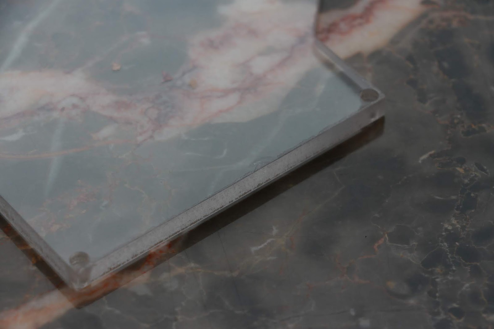
My first attempt led to some chip melting and the edges have poor finish (was at ~10k RPM and 45 IPM). I thought I was going fast enough but I guess now. Also the bore for the screw heads to sit in is undersized likely due to some melting.
 |
| Plate. |
 |
| Sad edge. |
I tried to go faster for a second time (60 IPM in program, with 120% feed rate in LinuxCNC, which comes out to 72 IPM) but still got melting. I held a brush up to the bit the whole time and this helped prevent chips from accumulating on the bit. I think the melting is because the acrylic was probably extruded and not cast (I don't know exactly what type it was, but it had clear plastic covers).
I had to use a drill to clear out the holes for the screws, but after that I could test fit it:
 |
| Not bad. |
The edge finish definitely needs work, but it should be easy to fix by changing acrylic type and putting in a dedicated finishing pass. I still need to make the top part of the enclosure and put in threaded inserts for the screws to grab. After that, if everything looks good, I will make more cases out of nice wood and not MDF.
I don't know how long I plan to stay at home due to the coronavirus outbreak shelter in place policy and school all being moved online now. If I stay I should be able to make more progress on this case and finish it up.