Thursday, April 16, 2020

DIY Numpad: Squareness

Over the last week I've done some more work, cutting out the USB slot, making a new case, and figuring out how to get better alignment. For the USB slot, I turned the case on it's side, zeroed in on the top left corner of face, and ran a simple pocketing operating to make the hole:
I clamped the case between a piece of MDF I screwed into the CNC table and a free piece of MDF.

Some shifting.
One clamp wasn't enough to hold it in place, and for the next case I used two clamps.

I began making another case, this time with another set of mirrored alignment holes. I also leveled out the waste board with a simple facing operation.
Added another hole at the top.
5x5 pocket cut out for the stock to be flat.
I ran the backside operation, which went smoothly. After I flipped over the part, I could still only get the holes on one side to line up with pins; the far side holes didn't line up perfectly. Now I realized what the problem was: my CNC's X and Y axes weren't perpendicular! I never realized this earlier because I never tested the squareness of my parts, and a double sided milling operation would effectively double the skew error. This also explains why the wood top case I made before doesn't line up well either since it was machined top side down (the error in screw hole position is effectively doubled by trying to mate a piece machined right side up and a piece top side down).

After some fiddling with the 8020 extrusions and the only square I had around, I think I have the axes dialed in fairly well. I just bought a machinist's square and you can clearly see the error in the last case:
Gap.
I lined up the holes I already made from the backside the best I could (effectively getting all the pins in with force so there would be a little error in all the hole positions, but no single hole far off like with the previous case) and continued on with the front side operations just to see how the case would turn out:
Actually not that bad.
Case in the light.
Surface finish questionable.
Better, but probably need to slow down.

Things lined up fairly well, I just couldn't use all the screw holes immediately because the aluminum plate was also made with the axis error. The next day I made the top part of the case:


Left: success; right: failed
Surface finish.
After heating, there is some optical aberration.
Same aberration.

The first one was scuffed because I didn't mount the middle piece down well, so the finishing pass knocked the floating piece from the middle contour, and the edge of the stock wasn't held down so when it was on the last pass, the thin edge vibrated and cause some terrible gouging. I fixed this on the second time around.

I tried heating the screw inserts, but it creates a visible defect in the clear acrylic. I just superglued in the rest of the inserts. for the next top case I make, I need to make the insert holes deeper since the screws hit the end before tightening the top to the bottom of the case.

Putting it together though:

Clear is the way to go.
The numpad looks far nicer that I expected. Things don't line up perfectly yet since the bottom holes were still made before the alignment, but after I make the changes to the insert holes and re-mill everything, the next case should go together perfectly.

I tried making another wood version of the top section of the case, but the crack in the wood caused some problems:
A crack in the left side caused the wood to become free to flap up and forced me to stop the program. I'll try again another time.

Friday, April 10, 2020

DIY Numpad: Machining Madness

I've spent the last week testing out different things to see how I could improve my ability to machine acrylic. Since I didn't want to have to buy new lead screws (which would mean spending more money and waiting for them to ship), I first tried to fix the ends of my lead screws. To prevent a screw from whipping, it needs to stay under some critical speed that is a function of it's length and the boundary conditions of the ends of the screw.

My screws are rather poorly installed, with only one end being fixed to the stepper motor and some part of the middle inside the anti-backlash nut. The other end was not fixed at all and there were no bearings to take the axial load from cutting. This was never a big issue before since I never ran my machine faster than 48 IPM during cutting. But now since I wanted to push 70-80 inches per minute without things resonating and stalling, I would have to fix this.

For the y-axis lead screw, the longest one in my CNC, I designed a few bearing blocks that could attach to the 8020 running under it. I started off with one to fix the far end of the screw in a simply supported way. This didn't really do much, and the axial load was still all taken by the motor.

Before adding more bearings and designing a system to tension the leadscrew, I tried adding some lubricant to the the lead screw and nut to reduce the sliding friction of the plastic on the metal. I read some posts online recommending adding just a little is actually very important to proper operation (which makes sense since the screw should have minimal friction with the nut, like with ball screws). I put a few drops of some generic anti-seize/rust-removing lubricant and the difference was like night and day. The x-axis no longer made any resonating noise at all when running over 80 IPM and y-axis ran much smoother too. (also the little rust that built up on the screw in some places was cleaned off by the lube and the nut running over it.

Next, I designed another bearing block to go on the motor side, so that I could tension the screw and take off the axial load from the motor.
I cut this out with my new end mills I bought a week earlier. I realized I lacked 1/4" endmills and bought two 1/4", 3 flute carbide end mills for general work, a 1/4" 2 flute carbide end mill for aluminum, and a 1/8" 2 flute carbide end mill. These were my first "real" end mills, in that they weren't from generic cheap 10 packs; I got them from drillman1 on eBay, with the two flute ones being Kyocera branded.
1/4" 3 flute carbide endmill
Cut from MDF.
The cutting went smoothly and I installed the block the next day:
On the other side, there is a bearing and a nut tightened to pull on the screw, and on this side the motor coupler acts as the nut and is pressing against the bearing. I only had normal bearings, not axial bearings or thrust bearings, so the coupler rubbing against the bearing was not ideal. However, this wasn't a big issue.

I tested this out for a bit, but still get resonance. During a test cut at 80 IPM, the y-axis lost some steps during some high-speed changes in direction.

Test pockets.
I was testing different feeds and speeds to see how I could get the best finish in acrylic. I realized that using conventional cutting for 2D contours left a much better finish on the walls:
Inside wall is rough while outside is smooth in a climb cut.
I tried two end mills: the single flutes I got a while back, and the two flutes I got last year for cutting aluminum. Both were cheap 10 packs so I could afford to test with them. Everyone says to use o-flute or single flute cutters to be able to run at the relatively high RPMs of a router (~10K RPM lower limit for me) and low feed rates of hobby machines. I was having serious trouble with chip evacuation and kept getting melting with my single flute. A little bit of plastic would get stuck in the flute and just ruin things. This is why I tried the 2 flute and higher RPMs; the two flute had a low helix angle and worked pretty well for getting chips out of the pocket and cavities.

Yesterday, after doing all that plastic testing the day before, I decided to do some practice for cutting out the acrylic cases for my numpad. Using the same 1/4" 3 flute end mill from earlier, I ran an adaptive tool path for roughing the pocket: 0.15" stepdown, 0.06" optimal load, 72 IPM. I tested this in some extra 1/2" thick acrylic I got when the seller accidentally sent 4"x4" squares instead of 5"x5".
Adaptive roughing.
Plastic chips!
It went really well, except for the lost steps in the middle of the program. I had to bump up the spindle speed to around 18K RPM to get the cut to sound good. I was afraid of heat generation from the higher surface speed, but it wasn't a problem at all. I had real chips (tons of them)! I kept a constant blast of air on the cut, but it wasn't really necessary; the chips pretty much ejected themselves out with no problem.

To try to further combat the lost steps without making another bearing block, I moved the motor side bearing block to the other side:
At the expense of table travel (I wasn't planning on making anything that big in the near future), this created a fixed end condition that made the screw whip much less. I just realized I should swap around the orientation of the bearing blocks to put the section in between in tension, but this worked really well. I still should put a bearing block on the motor side, but that can wait for now.

Today, I got around to really testing out making a numpad case in the 5"x5" stock. With all the fixes and things I learned for cutting the acrylic, I felt confident I could make this work.

This needed to be a two-sided setup since I needed to cut out the holes for the screw heads on the back side, then cut out the pocket, lip, and perimeter on the front side.

Back side.
Front side.
I aligned the two sides by drilling out the screw holes deeper than the bottom and using pins to align after flipping. I could only align the two holes along the bottom right faces since those were the only ones symmetric around my flip axis.
Screw heads opened up and holes drilled.
After flipping and cutting the pocket (1/4" for roughing, and 1/8" for getting the corners and finishing the walls):
The edge of the floor has a lip since I forgot to
re-zero the z-axis after swapping 1/8" cutters.


When doing the finishing with the 1/8" end mill, I started with the single flute cutter I had, but it created a really poor surface finish and the cutting wasn't consistent (edge didn't perfectly line up in some places. Swapping over to my new 1/8" end mill and running the program again gave a much cleaner result.

After these steps I realized there some sort of alignment issue but I couldn't really tell what exactly was wrong. I tried to test fit a plate and PCB into the pocket, but the corner holes didn't exactly line up. I just continued on since this was just a test.

Still using the new end mill, the lip for the plate and the edge cut went perfectly. Despite going only at 48 IPM and running at around 12K RPM, I had no issues with melting through the whole depth of the cut. I'm pretty much never going to go back to my old end mills; these may be more expensive but you get what you pay for: the quality and sharpness of the new 1/4" and 1/8" far exceeds the generics from China.

When the lip was being cut, I realized what the issue was. The two pins I used for aligning the bottom edge weren't enough to keep the stock perfectly aligned. The bottom was well-aligned, but the top could still skew a little. This caused the holes on the far side to not line up:
Right side holes are mis-aligned.
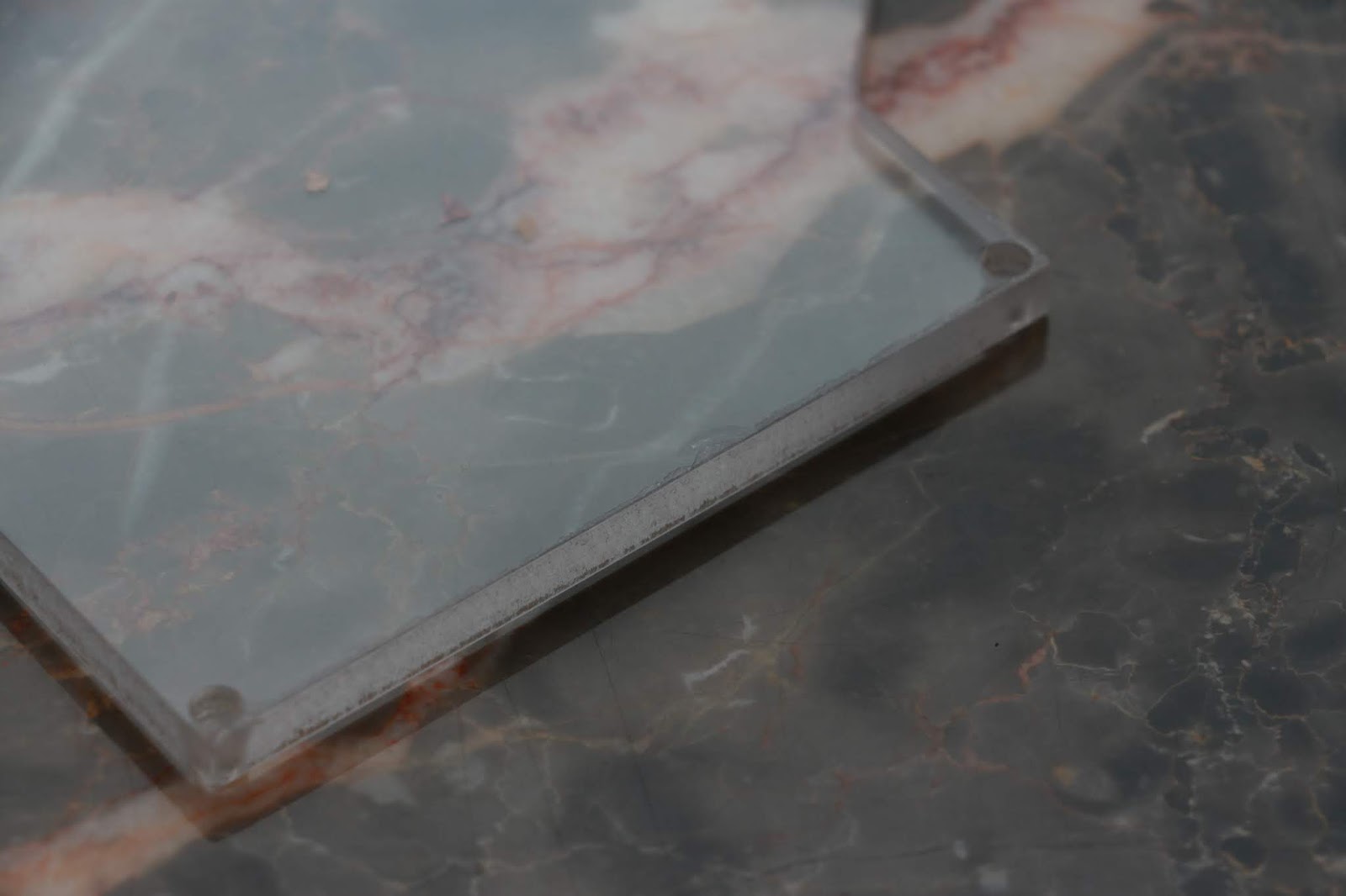
Case backside with the PCB inside.
However, everything else fit perfectly. I can still use this case to test cutting out the top side USB hole. (I plan on aligning the case vertically but still need to figure out how to set up my work piece origin in a reliable way.) Next time, I just need to add another alignment hole to drill out on the other side. The frosted finish of the outside is really nice and has just the right amount of diffusion.

Wednesday, April 1, 2020

DIY Numpad: First Completed Prototype!

I machined a top part of the case out of some oak wood; the plank had some internal cracks and as a result after being cut out it broke into a few pieces (I'll need to find some better and denser woods later):
Oof.
 I glued the pieces together the best I could and applied some polyurethane finish:
Uncoated.
I put in the 4-40 threaded inserts into the holes (they fit snugly with a little of pressure) and secured them with a little bit of superglue:
Perfect fit.
Screwing the top on:
Not too bad.
I now need to make the body out of the nicer wood too, but for now seeing everything together was big moment in the project.

The glued edge doesn't line up. You can also see the chipped clear plate with the poor surface finish.
I'm also a ran a few tests in acrylic to see try to find the right feeds and speeds to prevent melting. I simply can't run my machine fast enough with my current lead screws (10 TPI) even at the router's lowest speed setting. I broke two endmills, both due to lost steps from resonance. I need go faster than 70 inches per minute but am unable to consistently. I need to install some bearing blocks to support the axial load (so it's not on the motor directly) and pretension the lead screws.

Okay finish on the floor but not on the walls.
Chipped the end mill on the screw.
I could get good floor finish with lower optimal loads and smaller stepovers even at low feedrates, as expected. I tried a finishing pass but the feedrate wasn't high enough and I just got a fuzzy edge.

I also tested out engraving with a V bit (for when I want to engrave a section of the aluminum plate):
Wingman.
Will need to see what to do about the acrylic; I want to find what the true upper limit of my feed rate is after fixing the current lead screws before looking at getting new lead screws.

Thursday, March 26, 2020

DIY Numpad: More Case Prototyping (and Nixie Clock Case)

I did some more prototyping of the case several weeks ago using a 3D printer (first time I actually used a 3D printer) to test out an opening for the USB port:
Freshly printed.
This was the second time I printed it; the first time I didn't have a brim and one of the edges peeled up. The screw holes are undersized as expected since the plastic will have some squishing outwards and after cooling there will be some internal stresses, but I don't plan on using this right now so it is fine. The plate fit on it just fine.

Since this week is spring break, I was able to go home and use my CNC. I made a few changes: I got a new spindle after the previous one died (and it wasn't worth replacing brushes and bearings), bought a new spindle mount, and finally mounted my e-stop button.
New router (variable speed!) and mount.

E-stop.
Yesterday, I finally got around to making the case for my nixie tube clock. I did a quick test pocket before making the case:
Test pocket. 3/8" straight cutter.
I used a facing operation for the top with and an adaptive clear for the pocket. I made a few changes for the final case: changing the chaining for the facing operation from smooth to linear (so the tool wouldn't suddenly engage more material in the smooth curve outward), leaving a finishing pass for the adaptive, and adding a 2D contour to cut out the box from the stock.

Not bad.
This looked really nice but there were a few problems. The x-axis lost steps in the middle on the operation twice and I had to re-touch off to re-zero my x axis. This was due to some resonance in the x-axis leadscrew, and I had to add some damping to the screw with my hand. I need to make a bearing support from the other side of the screw, or use faster leadscrews (for a future upgrade). Secondly, my finishing pass was too aggressive (0.02" axial and radial stock to leave) and I think the thick double-sided tape had more deflection than that. I tried to pocket the entire depth of the pocket for the finishing in one pass and the final pocket was exactly 0.04" too thin. As a result I had to manually route the pocket a little bigger for the PCB to fit.

Pocket too small. Looks nice though.
I had to sand the top to remove some gouges in the stock.
Gained a case but lost a tube.
In my carelessness of handling my clock a tube dropped onto the ground and broke. A replacement is on the way.

Cracked tube.
 (update: new tube installed!)


Today I just wanted to run a quick job to test out a clear plate on the bottom of my numpad case (last week I got the APA102 RGB LEDs to work with SPI so now there are nice colors to see). I had some 1/4" acrylic to test this out in.

My first attempt led to some chip melting and the edges have poor finish (was at ~10k RPM and 45 IPM). I thought I was going fast enough but I guess now. Also the bore for the screw heads to sit in is undersized likely due to some melting.
Plate.
Sad edge.
I tried to go faster for a second time (60 IPM in program, with 120% feed rate in LinuxCNC, which comes out to 72 IPM) but still got melting. I held a brush up to the bit the whole time and this helped prevent chips from accumulating on the bit. I think the melting is because the acrylic was probably extruded and not cast (I don't know exactly what type it was, but it had clear plastic covers).

I had to use a drill to clear out the holes for the screws, but after that I could test fit it:
Not bad.
The edge finish definitely needs work, but it should be easy to fix by changing acrylic type and putting in a dedicated finishing pass. I still need to make the top part of the enclosure and put in threaded inserts for the screws to grab. After that, if everything looks good, I will make more cases out of nice wood and not MDF.


I don't know how long I plan to stay at home due to the coronavirus outbreak shelter in place policy and school all being moved online now. If I stay I should be able to make more progress on this case and finish it up.

Tuesday, December 24, 2019

Step Stool

Yesterday I put together a quick project: a step stool.

Finished product. Step stool!


My mom needed a small stool to go in the kitchen so she could reach some of the plates stored on higher shelves, but it had to be short enough to pass under the lower cabinets.

Finished CAD model.
Legs, also with dogbone for the inner corners.
CAM.
Time to cut it out on the CNC. I used some crappy plywood I had laying around; I wish I had better quality wood so it would look nicer but this wasn't too bad. During the cutting operation, the router's rotation started becoming intermittent and stopped working altogether. I thought the router finally failed but opening it up revealed a disconnected wire. After reattaching it and cleaning out some of the accumulated dust, the cutting went smoothly.

Cutting complete.
Free parts.
The tabs were a little large in one dimension and I just used the router to hand remove a bit of the wood for everything to fit together. Once I fixed that, I friction fit everything together with a hammer. Some sanding and a coating of wood poly later I had the final product:

Step stool in the corner.
I got really lucky that the plywood was only around 0.7 inches thick while in CAD everything assumed 0.75" thick wood. This effectively added just the right amount of margin to the tabs and tab holes to account for CNC's lack of rigidity. In the end, it all turned out nicely.