With another year gone, it's time for another recap. I think 2022 has been the year I've taken the most photos.


With another year gone, it's time for another recap. I think 2022 has been the year I've taken the most photos.
My friend owns a ribbon microphone, which have notoriously low output levels even after their internal transformers steps up the output, and always need to crank the gain up to the max and use noise reduction to get anything usable. A common solution is to use an in-line preamp such as the Cloudlifter and the FetHead. I wanted to see if I could make my own amplifier after seeing a small snippet on ribbon microphone amplifiers in the Art of Electronics.
After a little bit of Googling, I came across reverse-engineered schematics for aforementioned amplifiers. They both use JFETs in a differential pair, which allow for the gates to be biased at 0V straight from the microphone, and are powered directly off of phantom power with the phantom power resistors as the load. The Cloudlifter has a cascode configuration of JFETs, while the FetHead is just a single device. Someone already made a FetHead clone, and to keep my project simple I essentially cloned this. I added a few changes to my PCB:
 |
| KiCAD Schematic. |
 |
| PCBs. |
 |
| Parts. |
 |
| Assembled. |
 |
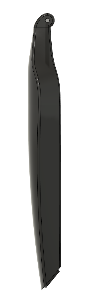
| Orthographic side view. |

 |
| Nice render with the tripod open. |
I had a much longer introduction written up in my draft document of this but now looking back at it, it's a little unnecessary. To summarize my thoughts; in an attempt to provide some motivating direct applications of what I have learned in classes, I want to begin writing about some projects that directly apply the theory from class to something more tangible. Hopefully they can demonstrate real-world issues that one can run into when implementing these concepts for real. This is also a good excuse for me to refresh my memory on many of these topics and provide a good written reference to hold on to.
Any errors/things that are unclear are on me. Hopefully there aren't too many and I'm not saying anything too wrong. 🤷♂️
Nothing technical about this post; just a recap of some photos I took throughout 2021 that I liked.


Comments: The forest one I like but feel the background should have either been more blurred (would have need a bigger aperture than the f/4 I had) or more in focus; currently it feels half-done both ways and is just a bit mushy. The Christmas one should probably be cropped tighter; the edges are messy. I should have framed the last one a little lower and wish the clouds were a little more dramatic.
I've also been going through some old photos and uploading/backdating a few I like.
This weekend I wanted to explore the simulation options within Fusion 360 since I had never used them before. I decided to take the layout from a previous class HW question since I already had the model in Fusion.
 |
| Folded-flexure comb drive resonator. |
Above is a folded-flexure comb drive MEMS resonator, although modeled in Fusion in millimeters instead of microns. It's a very well studied design, where the resonance frequency is mainly determined by the shuttle mass and the spring constants of the folded-flexure. I though this would be a good test since I know the equations for the spring constants of these beams and have done the analysis for these devices before.
How these devices normally work is that the center moving mass is set to a certain DC voltage, and then an AC signal is applied to one of the side combs. When the AC signal's frequency matches the resonance frequency of the center mass, the center mass will begin to oscillate significantly and the teeth in the combs will slide past each other, causing a change in capacitance at the other side (the output port). The change in capacitance will induce a current at the output comb that can be sensed, and it will have maximum amplitude at the resonant frequency.